The nematic (N) phase is the simplest known phase among all the liquid crystalline phases. The distribution of the centers of the mass of the molecules in the medium is liquid like. In the nematic phase the molecules have a long range orientational order but no translational order. Usually, nematic liquid crystals made of rod-like molecules have cylindrical symmetry i.e. uniaxial. The long axes of the molecules are on an average oriented about a specific direction, which is denoted by a unit vector n, called the director. The nematic director n is a dimensionless apolar vector i.e., n and -n are indistinguishable.
 |
| Figure 1.1: Schematic diagram of the molecular distribution in the nematic phase, and n is the director. |
The liquid crystal is enclosed between two conducting glass plates with a gap L. Let the plates lie in the x-y plane and the director n be parallel to the x-axis. The dielectric anisotropy Δϵ of the liquid crystal is positive. If an electric field E is applied along the z-axis, the dielectric energy is lowered by a tilting of the director. In the most general case, the director is anchored on both the surfaces with a pretilt angle θ(0) = θ(L). The tilt angle θ(z) is a function of the coordinate z and reaches a maximum value θm at z = L/2. The gradient of the tilt angle of the director increases the elastic energy. There are four possible boundary conditions depending upon the anchoring energy and the pretilt at the surface of the cell.
- Zero pretilt angle and infinite surface anchoring energy : The angle at the surface is independent of electric field [θ(0) = θ(L) = θ0 = 0].
- Zero pretilt but finite anchoring energy : The angle at the surface is a function of the electric field, θ0 = θ(V).
- Non-zero pretilt but infinite anchoring energy : The angle at the surface is fixed (θt = pretilt angle) and independent of electric field.
- Both non-zero pretilt and finite anchoring energy : With an applied electric field the angle at the surface deviates. This deviation increases with the field.
 |
| Figure 1.2: The distribution of director field under an applied electric field. The glass plates are shown in 2D while the director profile in the interior of the cell is shown only in one plane. |
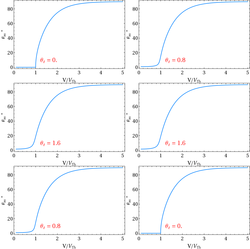
- Here we consider the 1st boundary condition i.e. zero pretilt angle and infinite surface anchoring energy. Director does not deform as long as applied electric field exceeds Fréedericksz threshold voltage. The mid-plane angle θm reaches 90o under high electric field.
 |
| Figure 1.3: Variation of mid-plane polar (tilt) angle θt as a function of applied voltage |
 |
| Figure 1.4: Animation of director deformation under electric field |
 |
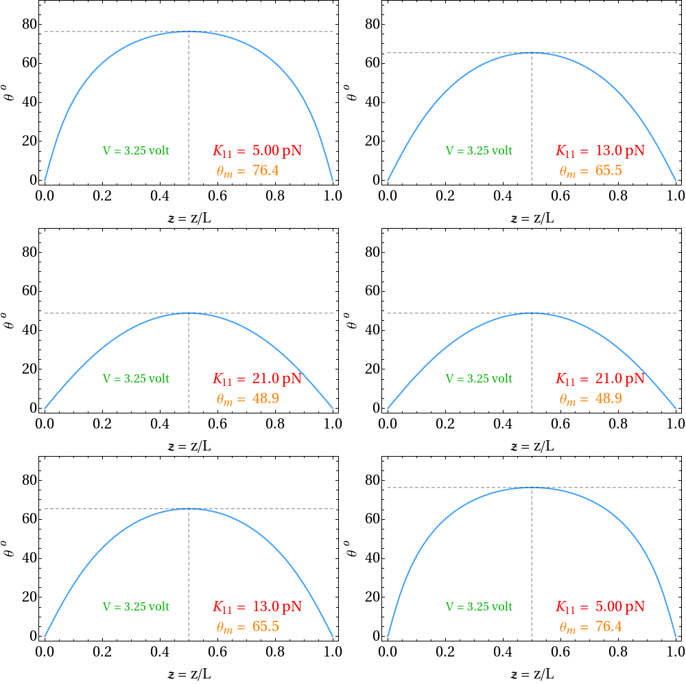
| Figure 1.6: Animation of director profile under electric field |
 |
| Figure 1.6: Gradient of polar angle as a function of reduced thickness (z/L). |
- Now we consider a condition of finite pretilt angle (say θt = 5o) and infinite anchoring energy.
 |
| Figure 1.7: Director deforms even at V < VTh i.e. there is no threshold voltage. |
 |
| Figure 1.8: Animation of director profile at fixed applied voltage (> VTh) for various splay elastic constant |
 |
| Figure 1.9: Gradient of polar angle at fixed applied voltage (> VTh) for various splay elastic constant |

